Wiring A Switch Receptacle
Installation | Testing | Video | Q&A | Tips | Warnings | Things You'll Need GFCI (ground fault circuit interrupter) receptacles are mandatory in kitchens, bathrooms, outdoor areas, and basements. Unlike traditional outlets, GFCI outlets measure the amperage in the outgoing current when you plug something in.

Gfci Outlet With Switch Wiring Diagram Free Wiring Diagram
Step 3: Remove the Wires. Disconnect the wires attached to the old outlet. Use the screwdriver (or tester) again to remove the screws holding the wires at the back of the outlet. You might only need to loosen them to pull the wire ends out. You can pull the entire outlet out when all the wires have been removed.
GFCI OUTLET WIRING AND RECEPTACLE (English). YouTube
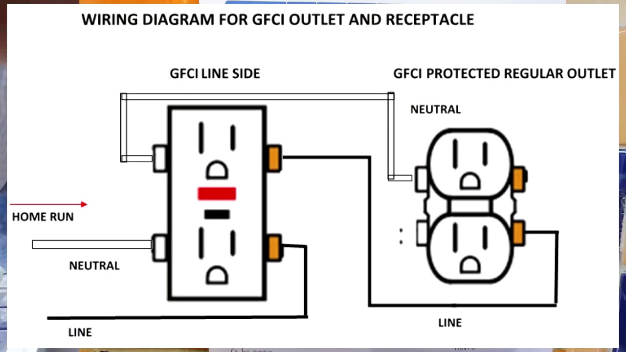
The wiring diagram for a GFCI outlet includes the necessary steps and connections to ensure proper installation. It outlines how to connect the incoming and outgoing wires, as well as the correct placement of the line and load terminals. By following the diagram carefully, homeowners and electricians can install a GFCI outlet correctly..

How to install and troubleshoot GFCI
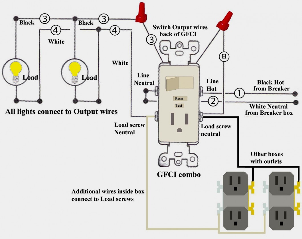
This page contains wiring diagrams for a ground fault circuit interrupter (gfci) with a built in switch, often called a gfci outlet switch combo. This device can be used for ground fault protection near water sources such as in a kitchen or bathroom where space is a minimum and both devices are needed.
Bathroom Gfci Outlet Wiring Diagram Collection
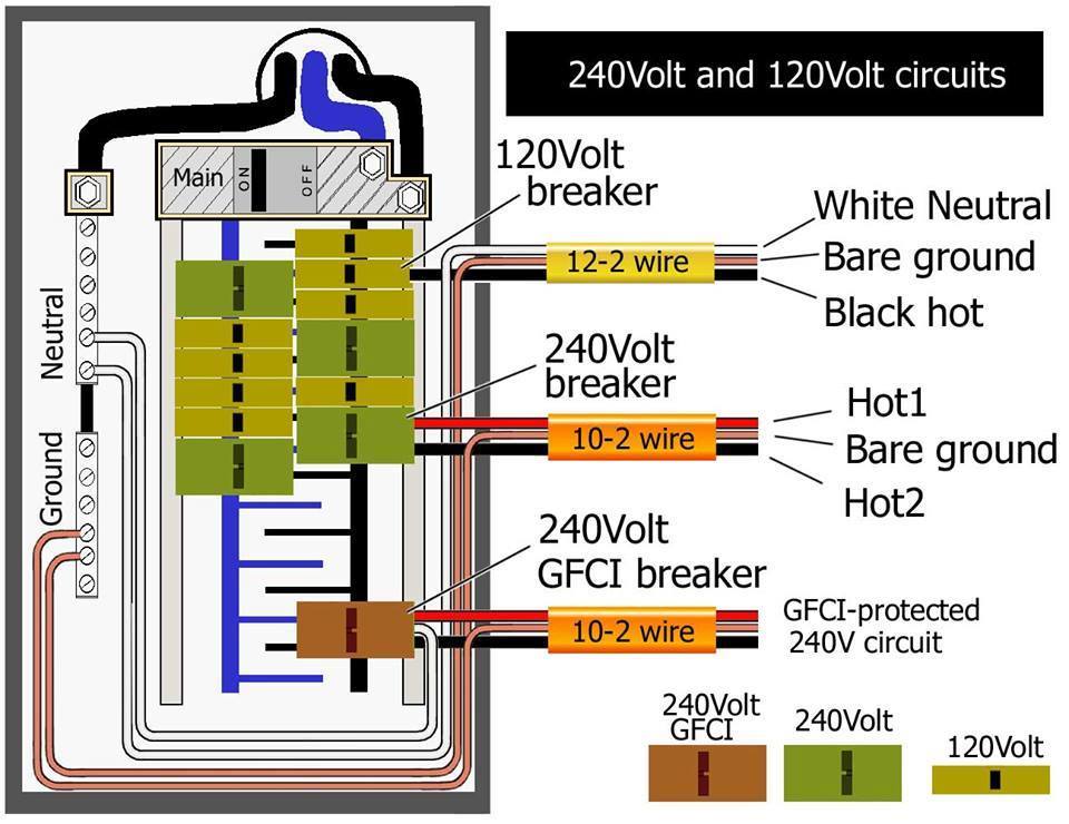
2 Tools for Wiring a GCFI Outlet GFCI outlets can be used several ways inside or outside a home. For example: An entire circuit can be protected by a single GFCI device if the GFCI receptacle is the first outlet on that circuit.

Wiring Gfci Schematic electrical How do I install a GFCI receptacle
Over 17,000 Products In Stock. We Ship Everywhere Fast!
Gfci Receptacle With A Light Fixture With An On/off Switch In Wiring
In other words, the outlet in GFCI can be turn ON/OFF via upper switch in the GFCI combo. To do this, simply connect the upper wire (there are two builtin wires on the back side of GFCI) to the line terminal of GFCI while the second wire should be wired to the incoming line (phase, live or hot) wire. Connect the ground / earth terminal to the.

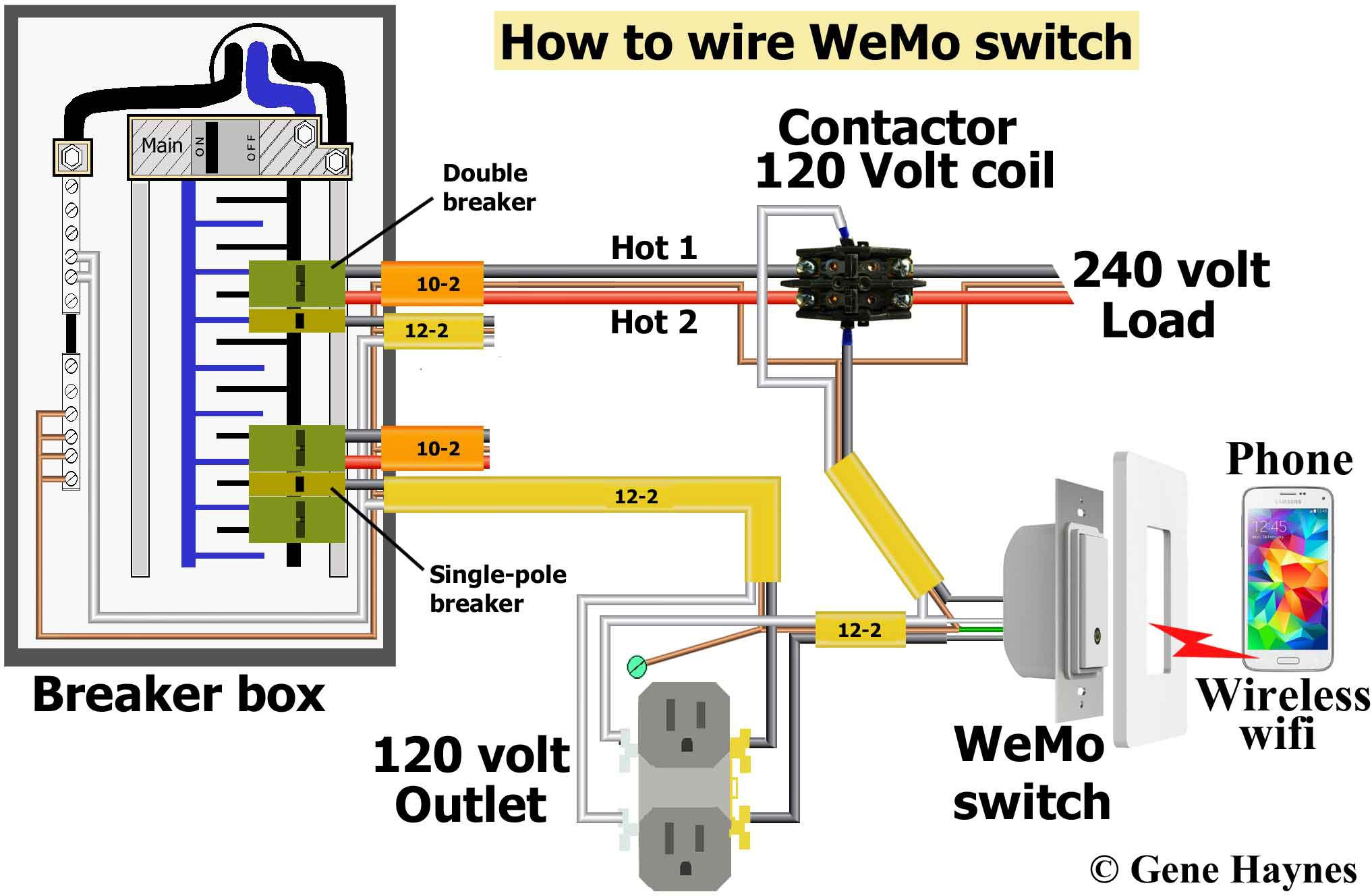
electrical dual GFCI circuits with multiple protected outlets, all
Make sure the RESET button on the face of the GFCI is pushed in. Then, press the TEST button; the RESET button will click and pop out; this shuts off the power to the outlet. Press the RESET button again to restore power. If desired, you can test the outlet with a neon circuit tester for proper wiring.
Cooper Gfci Outlet Wiring Diagram Wiring23
The wiring diagram for a GFCI outlet typically follows a specific pattern. The line side wires, which include the hot wire (black), the neutral wire (white), and the ground wire (green or bare copper), are connected to the corresponding line side terminals of the GFCI outlet.
Gfci Outlet Wiring Diagram Electrical Engineering Books
Learn how to install and use Eaton's GFCI receptacles, which provide reliable and safe protection from electrical hazards in various settings. This PDF guide also covers the latest updates from the NEC 2020 code and offers tips and best practices for GFCI installation.

Wiring Gfci Schematic Wiring Diagram Schemas
Looking for Electricians in England? Read Reviews And View Previous Work. Read Reviews & Compare Local Electricians. Save Time. Post Your Job Today!
Light Switch Schematic Combo Wiring Wiring Diagram Gfci Outlet
1 - for each hot and neutral wire entering the box. 1 - for all of the ground wires combined. 1 - for all of the cable clamps combined (if any) 2 - for each device (switch or outlet—but not light fixtures) Multiply the total by 2 for 14-gauge wire and 2.25 for 12-gauge wire to get the minimum box size required in cubic inches.

Leviton Gfci Receptacle Wiring Diagram Free Wiring Diagram
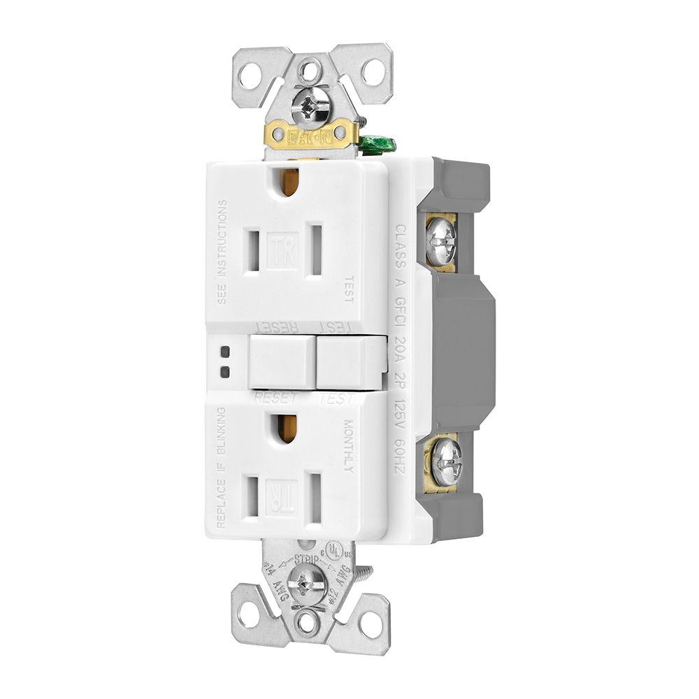
GFCI also known as "Ground Fault Circuit Interrupter" is a protective device which automatically detects the ground faults and leakage current and provides personal protection against electrocution. GFCI as an outlet / receptacle, combo or circuit breaker, automatically cuts off the main power supply within millisecond against electric shock.

Pin page
This page contains wiring diagrams for ground fault circuit interrupter (gfci) receptacles. Included are diagrams for multiple gfci's, a protected standard duplex receptacle, and a protected light fixture. Wiring for a switch and gfci receptacle in the same box is also shown.

Gfci Schematic Wiring Diagram
Steps for a GFCI Outlet Wiring Upgrade. First, turn off the power to the circuit you'll be working on. Take off the cover plate and unscrew the outlet from the box. Disconnect the wires and remove the old outlet. At the back of the GFCI are screw terminals marked "load" and "line.". The single screw at the bottom is the grounding screw.

Wiring Diagram For A Gfci Receptacle Outlet Diagrama De Poppy Daily
Wiring a GFCI outlet should be done with attention to detail and you must test the outlet when you complete to ensure it is working properly. GFCI Outlet Wiring Diagram -(pdf, 55kb) Back to Wiring Diagrams Home. Click the icons below to get our NEC ® compliant Electrical Calc Elite or Electric Toolkit, available for Android and iOS. The.
